

Venkatasamy Ramesh*
Functional consultant & Former Consultant at National Grid SA, India. venkatesh.engg.consultants@gmail.com
Abstract: #
A Digital Twin (DT) is a digital replica of a physical object. In this presentation, Digital twins are currently mostly used in power systems for visualization or to bring data together, validate software or extract data and do maintenance remotely. We did this DT to enable the remote accessing of RTUs (Remote Terminal Units), SAS (Substation Automation Systems), and protection Systems, and validate requirements on the digital model. Unlike other regions in (Name of the organization not mentioned here), the southern Telecom &SCADA team was in the field of implementing the Digital Twin technology as continuous improvement works during 2009-2010, which was named as “Benefits Oriented Zero Cost projects in Communication Automation Technologies” (hereafter BOPCAS). Communication Automation was a rapidly growing area of technology that is seeing growing interest within the power system. The Zero cost projects were the real history projects which were implemented in electric power systems have a wide impact on the prevention of blackouts, less maintenance cost enables the Control center to take quick decision making in the operation and maintenance field. In earlier years there were no such Digital Twin technologies provided by the project execution, hence the power system network has faced lots of problems and delays in execution in operation, and maintenance. Today the world is facing an economic crisis and power system problems, SCADA & Communication team plays an important role in minimizing the impact of widespread power system Disturbances by having implemented the Benefits Oriented Zero Cost projects since 2009. The purpose of this paper locates the notion of technological revolutions in the Communication Automation Systems in southern power system effort to understand innovation and to identify the regularities and discontinuities in the process of manufacturers’ design. All the ambiguities of the Manufacturing design stage were corrected by the team and are up to the standards and operational with good results to date. It fulfills the patterns observed in the evolution of Technical change and the interrelations with the context that shape the rhythm and direction of innovation. On this basis, it defines technological revolutions and examines their structure and the role that they play in rejuvenating the whole system through the application of the accompanying techno-economic paradigm. All the Zero Cost Projects( no money spent for the materials, utilized the old materials ) which have been implemented in the Najran power system are without any additional equipment, materials, and additional Project Costs which helps the power systems in Najran to tackle the various techno-economic problems. It renders trust worth Services and time-proven systems to Consumers, operation and Control Sections, and the Transmission section of Najran.
Key Words: Millions Cost to Zero Cost Projects – Reduces Income loss – No maintenance cost – Serves as Backbone to Master Station
1 Introduction #
A digital twin is a virtual representation of a real-world object or system. Such a digital carbon copy gives developers many interesting opportunities. For instance, they can test their software, and they can run all kinds of simulations and what-if scenarios on the digital twin long before the physical system is available. This way they can drastically reduce development time and boost first-time right deployment. In this talk, we give a definition of ‘being a twin’ using testing equivalences and conformance relations. We then give methodologies to actual create requirements and automatically validate these requirements using model-based testing. We apply our definition and methodology to a factory model representative of typical systems used and developed by our customers. Unlike other regions in the world, the Najran region from the south of electricity sectors has implemented many historical Zero cost projects in the electricity sectors in HV, LV Substations, and Control centers in terms of low-income loss to the distribution department and ensuring uninterrupted power to 150,0000 Consumers, the introduction of Zero cost projects, modernization and a new approach for operation and maintenance. All of the Projects which have been implemented are based on the recycled process which in turn improves the economic performance of the running and maintenance costs of the power system. This Zero cost technology projects are known as “Najran Blooms with Zero Cost Projects” or “Million costs to Zero cost Projects” has wide positive effects on the Key Performance Indices (KPIs) in the Najran region. In addition to the Zero Cost Projects, Najran National Grid is launching various precautionary measures to the Communication systems for fail Safe operation by implementing various modifications and designs to suit the existing systems for upgrading in an efficient manner.
In such Zero Cost Projects, Najran National Grid will implement these projects in other inter-regional Communication Systems in an efficient manner. Three Major dimensions can be identified in such a project (1) Technical dimensions, (2) Economical dimensions, and (3) Safe operation dimensions. Although the Najran National Grid team had devised many (7) Zero Cost Projects, only five topics will be introduced in this paper.
- Remote Reset of RTUs in HV & LV Stations
- Remote Access and Remote Configuration of RTUs
- Continuous Monitoring of UPS and DC System ( 125 & 48 V DC ) system voltage at Control Centres from remote Stations HV & LV
- Online monitoring of Fibre Splicing
- Integration of Radio systems with Fibre network
All of the above Projects that we designed, engineered, and implemented in Najran were with Zero Cost; no money has been spent from the National Grid department’s budget. All the projects are operational in the southern region., all the materials and equipment have been used in these projects are based on the recycling technique, hence no additional cost for the projects and achieved the goals in a short time [1][3]
2 Scalable Architecture #
2.1 Remote Reset of RTUs (Remote Terminal Units) – Zero Cost Project for 14 Substations in Najran: #
RTUs in Remote Substations are sometimes subject to Hang up (Sleep mode or Image Mode ) that time if any 132 KV line feeders or 33 KV Feeders or 13.8 KV feeders trip, the Control centre tries to Close the CB, but this Command cannot reach to that Circuit Breaker due to that RTU is in Hang up condition and. RTU needs to be reset manually by any SCADA Personnel traveling to that remote S/S and then the Control centre can give close Commands to those CBs. [2][3]
To overcome such above problems, Telecom. Group had designed a new Zero Cost mechanism to reset the particular remote Station RTU from the southern control canter Desk; this facility is available in Najran since 2009. To reset the RTUs in all Substations in the southern Area, Control Centre personnel shall do it by themselves, with no need for assistance from SCADA Personnel for re-setting the RTU. Reset of RTU facility in Najran area gives trust worth Services and time-proven systems to the Consumer, Operation, and Control Sections of the electricity sector in southern regions.
All materials used in this project were utilized by the recycling process, hence no money was spent from SEC budget, with available materials in the Southern electricity sector for this Remote Reset of RTUs mechanism implemented within one month in 14 Substation’s RTUs in the southern Area. The control centre can access to reset the remote substation RTUs from the Control centre table and hence providing flexibility to the Control centre operations.
When the RTU is in sleep mode, the remote reset of RTUs mechanism is helpful to the distribution maintenance team, Transmission line maintenance team, and Control centre when there is any 13.8 KV poles getting fire, also any foreign object (polythene papers or clothes, etc) touching or hanging on HV transmission lines and need to open the CBs at Substations, the CC shall to press the related reset button for the substation to reset the RTU which is in sleep mode, within 2 minutes the RTU will be in service to open the CBs[1][4].
2.2 Remote Reset of RTUs Mechanism in power system #
To reset the RTUs in Remote Substations in Najran, Just press the button in the Key telephone button the command will be sent to that particular RTU through MDFOTE and DPLC links and then the RTU will rest within 2 minutes and the RTU becomes operational state without the involvement of SCADA & Telecom. Staff and network operators. Each station RTU reset is independent of the other All the RTU Wirings are safe and secured properly, ensuring more reliability of RTUs operation due to the presence of Remote reset of RTUs from the Control Centre Screen and Communication room as well.
RTU at Remote Substation Which is under hang Up Condition Need Reset from LDC

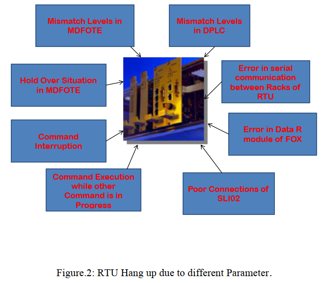
2.3 RTU Hang Up (Sleep Mode & Image Mode) Reasons. #
RTUs or any electronic equipment which operates with a high baud rate are sometimes subject to hang-up (sleep mode or image mode). Hang up of electronic equipment due to the following reasons [5][7].
- Mismatch levels in MDFOTE link
- Mismatch level in DPLC link
- Hold Over situation in MDFOTE
- Error in serial Communication ports of RTU
- Command Interruption
- Error in Data module
- Any other command in progress
- Poor connections
-
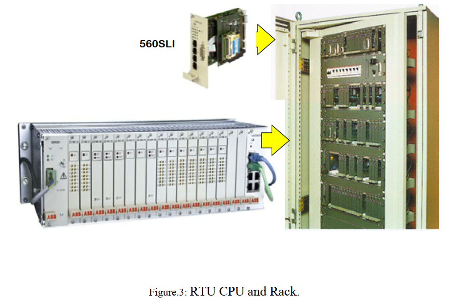
2.4 RTU 560 CPU and Its Racks. #
RTU modules are operating with 24 V DC and 5 V DC Voltages; CPU module is with flash memory and operates with different Data Speed as set by the maintenance personnel by RTU Software tool. In Najran all the 132 KV RTUs are operating with a data speed of 19 200 b/s [3]
2.5 Merits of Remote Reset of RTUs in Najran. #
- No need to travel to the remote Substation to reset the RTU [1].
- No need Operator to travel to the Substation to close the CB when RTU hangs up during Day or Night time.
- Cuts down Time
- Cuts loss of revenue to electricity departments
- Ensures RTUs reliability and thus maintains Reliable Electricity to Customers
- Remote reset of RTU facilitates the CC dispatcher to reset the particular RTU in the Substation by pressing the button in the Telephone set in any kind of emergency situation, Reset mechanism is kept at the control centre .
- Reduces traveling time & traveling expenditure.
- Reduces Operational Costs.
2.6 Remote Access and Remote Configuration of RTUs , SASs, and Protection Systems #
This facility is available only in this electricity sector, modification of any Data in a remote Substation’s RTU normally a maintenance person needs to travel to that substation, but in Najran no need to travel to the remote substations, all the Data modification shall be done at Najran CPS Communication Room itself. Also, this facility serves as the backbone of the Master station computers[1][2].
2.7 Remote Access and Remote Configuration of RTUs #
Any modification or addition of Data in RTUs in a Remote substation needs a SCADA staff to travel to that Substation and then perform the Data modification with Laptop, also needs the Operator to be present till the RTU becomes in operation mode.
As an example S/S E RTU in the southern Area if it needs configuration change, SCADA Staff need to travel from headquarters to S/S E i.e. 300 Kms away from CC After implementing this facility no need to travel to any of the 132 KV S/Ss for data modification [5].
2.8 Serves as the backbone #
In case of the Master station, the computer fails, an inoperative stage arises or any emergency at that time this Remote Access facility will perform all operations such as Command execution, back indications, alarms, and measurements shall be collected from the remote Substations. It serves as the backbone mechanism for the Master station. RTU Training for maintenance employees shall be performed with different station RTUs in one place at a reduced cost. A behavioral study of different RTUs shall be carried out[1].
2.9 Accessing RTU Locally at Substation #
Here the Picture shows that the RTU is being accessed locally at Substation Need to travel to that Substation & network Operator is required to close the tripped CBs while uploading the RTU
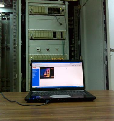
Figure.4: Accessing the RTU locally at Substation with Laptop.
3 Digital Twin design and execution #
3.1 Accessing the RTU, SAS, Protection systems, DC systems remotely from Control centre #

Figure.5: Accessing the Remote Station RTU, SAS, Protection Systems, and DC systems from Control Centre.
Here the Flow diagram shows that the RTUs, SAS system, Protection systems, and DC system 125&48V dc shall be accessed through related telecom panels and brought to the control centre screen. From the Control centre all the downloading/uploading of data and creation and modification of data for all the utilities can be done from the control centre. Normally to download/upload data in above said asset utilities need to travel to each substation, but after implementing the Digital Twin facilities it is very easy from the control centre building to view and modify the data.
The HMI ports of RTUs, SAS, protection panels, and DC systems shall be carefully interfaced at each substation E, D, C, B, A, and CC with suitable connections[3] [4]
3.2 RTU remote Accessing #
RTU Process signal flow diagram shows how the RTU 560 remote accessing and how the signals such as commands, indications, alarms, and measurements are processed from the Substation’s Switch Gears
 3.3 Merits of Remote Access and remote Configuration of RTUs., SAS, Protection systems, and DC systems #
- No travel expenditure.
- Cuts downtime.
- No additional manpower (operator or maintenance personnel).
- During a Blackout situation, this Digital Twin technology is very much useful to know the power system parameters from the Control center.
- Serves as the backbone of the Master station. If the Master Station Computer system fails or is in the inoperative stage that time this Remote Accessing for RTU will take care of the activities of the Master Station to open and close the switch gears.
- Training for maintenance personnel shall be carried out with different station RTUs, SAS, protection systems, and DC systems in one place
-
4 Continuous Monitoring of DC System Voltage at Control centers #
The continual improvement of Telecom & SCADA, Group had implemented the project of monitoring 125 and 48 V DC System Voltage at the control center with old scrap materials, recycle process technique was followed without spending any money from the electricity sector’s Budget
The improvement group completed this implementation of DC System Voltage Monitoring at the control center with Zero cost during 2009-2010. Earlier there was no such monitoring of the DC system Voltage at the control center, but now all the 132 KV S/Ss and 33 KV S/Ss have been implemented for the continuous monitoring of the DC system Voltage at the Control Centre screen. SCADA & Telecom Group used Scrap materials -Transducers, cables, and fixtures.
The old Voltage Transducers were suitably modified to comply with DC system voltage and tested for its accuracy and then installed at various substations and communicated the voltage readings to the Control center. Now 125&48 DC voltage of all Substations, SCADA UPS were implemented at Control center. Old Transducers were with 0-1mA which was not compatible with the new SCADA System, but SCADA & Telecom Group had done suitable by conversion in the configuration in all RTUs and made suitably and comply with SCADA systems without any additional cost and materials[7]
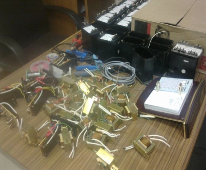
Figure .7: Old & released transducers being modified for DC system voltage monitoring
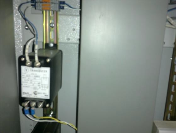
Figure..8: Modified Transducer with 0-1mA is under Testing at the Substation at Najran.
These Transducers were removed from the old SCADA System, checked for their accuracy and calibrated for their linear characteristics, and then installed for the DC system voltage monitoring in each substation. After the installation of transducers at each Substation several tests were carried out such as the discharge and recharge of battery banks and observing the linearity of the magnitude of DC voltages at the Control center Screen. All the results are satisfactory and up to the standards [7].
4.1 Continuous Monitoring of DC System Voltage from Remote Substations. #
Earlier there was no monitoring facility for the DC system voltages to appear at LDC, but now 48 & 125 V DC Voltages of different Substations in Najran are appearing at LDC Najran screen.
Fig. 9 shows the dc system voltage levels from various substations (132 & 33 KV ) that were being monitored for 48 V, and 125 V dc systems. The provision also has been implemented to monitor the SCADA UPS system voltage at the Control center [1][7].
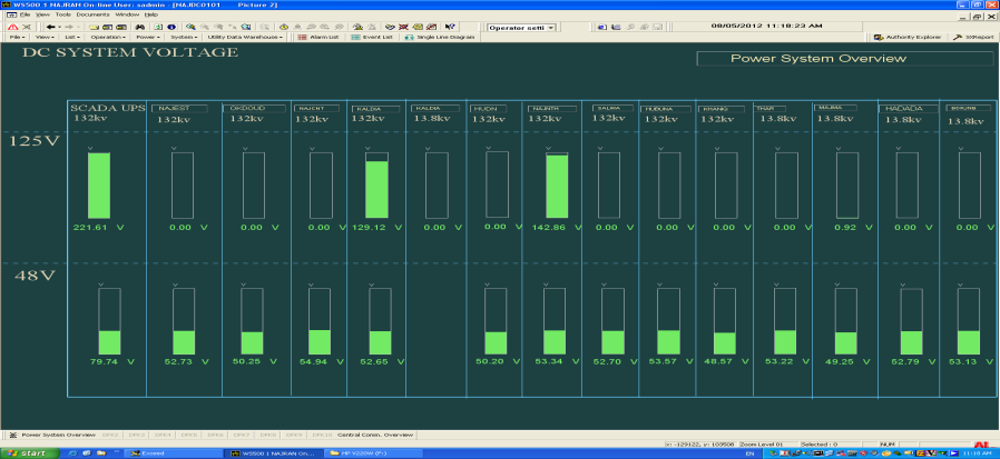
Figure..9: Control centre Screen Displays the DC System Voltage and SCADA UPS Voltage.
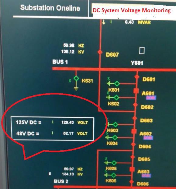
Figure 10: DC system voltage display in individual substation screen at the control centre
4.2. Worthiness of DC system & SCADA UPS System Voltage Monitoring at Control Centre #
- During a Blackout situation the DC Voltage & SCADA UPS Voltage monitoring in different substations are helpful to the S/S maintenance team as well as to the Control centre dispatcher.
- Assume the alarm card in RTU for Charger Alarms is defective or has no connection, that time this DC system Voltage monitoring at the Control centre is useful.
- Any dip in power system voltage occurs that time study the DC system performance shall be known with time & date at the Control centre itself.
- Automatic boost voltage function if it happened in DC system, then it will be known for Date & time.
- Chargers having poor performance and poor voltage regulation characteristics shall be easily known from the daily CC voltage log.
- Anyoneone needs to know the present level of DC voltage, no need to travel to the Substation which is 400 or more Km distance, just visit and request the Control centre dispatcher for the present status of DC system in a particular Substation.
- Comparison of different DC systems Voltage in different Substation collectively at one place at Control Centre, no need to travel different substations.
- Cuts Travelling time & traveling expenditure drastically.
- If both chargers are having problems due to Ac input failure, that time we will come to know the Voltage level of that DC system, Voltage level is enough to withstand up to 10 hours or 5 hours so that the DC system maintenance personnel will rush to the Substation according to the Voltage level indicated at LDC screen.
- Control centre dispatcher and dc system maintenance teams relieve tension and they will be strong in psychologically too.
- Daily Log shall be prepared at headquarters without visiting each Substation.
- Behavioral study of DC system for continuous service
4.3. Remote Charging and Discharging of DC system is under progress : #
The improvement team also studied the possible steps to implement the remote charging and discharging of the valve-regulated battery bank (maintenance-free battery bank ) in the power system. If this facility is to be implemented in the electricity sector, then no need to travel or go to the remote substations for discharging and re- charging the battery banks. This is applicable only to valve-regulated battery banks. Maintenance of DC system group shall able to give command from the headquarters to open command to the chargers to switch off the AC input source to the rectifier while discharging the voltage levels shall be obtained from the Control centre ( if already implemented the remote monitoring of DC systems ) screen. After discharging with a safe operating voltage level, the close command will be executed by the DC system maintenance personnel and then the rectifier will be in service and voltage will be monitored continuously at the Control centre screen.
5 Strategic Decision #
5.1 Plugging Loopholes in +48 V grounded communication systems #
All the SCADA & Communication equipment in the southern area was free from circulation currents from the Substation ground system by having implemented the separate ground system for the Communication system. Also all Substations we have removed the shield wire of the Control & signal cables at the Switch gears panels side and have an earth connection at the communication equipment side. This ensures that the communication equipment such as RTU, MDFOTE, DPLC, SDH, and DPABX systems are free from circulation currents and hence the operation of all SCADA & Telecom equipment are in safe environments at Najran. All the voice circuits MDF & E1 circuits were equipped with suitable protectors to protect against the surge in the networks
EFFECTS OF UN CLEARED E/FAULT CURRENTS ON COMMUNICATION SYSTEMS WITH +48 V GROUNDED
Un – Cleared E/F Current arises due to 1. NO DC for tripping . 2. Relay may inoperative state . 3. Mechanical problem of CB

HOW COMMUNICATION EQUIPMENTS GETTING AFFECTED WITH CIRCULATION CURRENTS IN SUBSTATIONS
When there is a Circulating current occur in any Substation and if it is persisting for long time say 1 to 3 minutes , the circulating current may flow in RTU ,DPLC and FOX cables cores and reach to the cabinets of RTU , DPLC and FOX., In RTU560 the Modules 23BE21/23 are having filed contact voltage as +48 V , Since the filed contact Voltage is positive ground , the Circulation currents with high magnitude may enter inside the 23BE21 modules according to the effective resistance of 23BE21 Modules and damage the complete 23BE21 modules .
- RTU-560 – 23BE21/23 modules may fail , if the circulation current magnitude is high the other modules 23AE21 , 23BA22 7 23 Ba20 may also fail
- FOX – 515 – SUB-H module is prone to damage due the Telephone line inside the Cable ttrench / cable duct due to circulation current in S/S
- DPLC -640- Power supply module may fail , DPLC balancing transformer and HF Hybrid may fail
HOW TO AVOID THE COMMUNICATION EQUIPMENTS FAIL FROM CIRCULATION CURRENTS FROM SUBSTATION
- Implement separate Ground system with MGB for Communication equipments , No connection with Substation ground system
- All the cables of RTU , FOX , DPLC , DPABX , SDH etc – The ground wires shall be earthed at communication cabinets only , other end no need .
Fig.11. Effects of Circulation currents on +48 V grounded Communication Systems
5.2 Command execution Successful Alarms #
Whenever Control Centres execute a command either open or close the CB in any substations in the Najran area, that time if any interlock in force or local /Remote switch is in local position or no 125 V DC , such conditions will not be permissive for the successful commands up to the Switch gears
.

Figure 12: Command execution successful alarm
When the command is not successful, the Control Centres immediately inform the SCADA & Communication crew that the command was not successful to open or close the CB in the substation and an abnormality report will be issued to SCADA & Communication crew even if the closing and opening of CB problems which are not related to the SCADA system. To overcome these problems for SCADA & Communication crew, in Najran we have implemented a feedback signal for each command executed by RTU, this feedback signal will be displayed at the Control Centre screen saying that the command executed by RTU was successful. This Command successful alarm in Najran relieves the SCADA & Telecom crew and also the Control Centre directly calls the substation crew to troubleshoot the control circuits of the CB. Such facilities in the southern electricity sector save in troubleshooting time
All the auto voltage (110-220 V) operating communication equipment such as the Radio system, ADAS system, and Chargers were connected with a 110 V source as safe operating voltage, in case any surge voltage occurs in the power source that will not affect electronic modules due to more reserve in voltage tolerance up to 220 V.
Double-stage fuse protection for Radio Base and repeater stations: in case any high voltage if it comes in low voltage distribution circuits, this high voltage will damage the electronic modules with successive stages, to avoid such damage Najran maintenance team has introduced one more fuse circuit which is outside the Radio equipment as a fail-safe system
RADIO Station Ground Connection: All the Radio Station ground connections were not mixed with the ground ( MGB ) from the tower ground connection due to the lightning stroke from the antenna (built-in self-lightening arrestor ) cable should not reach the Radio station and affecting the power supply modules of Radio station.
6 Conclusions #
CAS (Communication Automation Systems) whatever facilities are not covered in the Substation Project by the contractors and which cannot be designed by the manufacturers are modified and designed by Najran SCADA & Telecom. Team with zero cost and achieved goals for the beneficial use of electricity sectors. After implementing these Communication Automation Facilities Najran had not faced any Abnormalities due to RTUs in all S/S with the Presence of mechanism
- Remote reset of RTUs from the Control center’s table
- Remote configuration of RTUs and
- remote configuration of Protection systems
- Remote monitoring of DC system voltages
Above mentioned Zero cost project’s effective mechanism has drastically null the emergency works and hence no additional expenditure also these Digital Twin facilities are much useful to the electricity sectors, especially in the crucial situations of COVID19 .
The maintenance cost and running costs have been drastically reduced since 2009. Now Najran is stepping into the 4th year for achievement in NO abnormalities, NO Overtime, and NO maintenance cost. SCADA & Telecom Group did other four Zero Cost Projects, but due to the limitation of presentation rules those projects have not been mentioned in this Paper [5][6]
7 Acknowledgement #
I sincerely thank my academic advisor and thesis Dr. N. Nanda Gopal, technical expert, and Director Eng. Fareed Al Asmari, Department Manager- National Grid south, KSA for his guidance and support throughout the preparation of this paper. Also, I am very thankful to Eng. Abdul Mohsin Ali Al Garni, Divisional Manager, SCADA & Communication South, KSA for their support in the preparation of this paper.
References #
- Mr. Hiromitsu Kumamoto & Ernest j. Henley – “Probabilistic risk Assessment and management for engineers and scientist” IEEE, Second Edition, the Year 1998
- Mr. Joseph Di Giacomo, editor in chief, department of Electrical Engg. Villanova University – “Digital Bus handbook”, IEEE Third Edition, the year 1998
- Dr. Muhammad H. Rashid, Purdue University at Fort Wayne – “ Spice Simulations of power electronics, IEEE – Second edition, the Year 2000
- Mr. William R. Blood. Jr – “ MECL System Design Handbook ” Motorola – Fourth Edition, the Year 2005
- QMS-Quality management systems ISO 9001:2015
- EMS-Environmental management systems ISO 14001:2015
- IEC 61850-7-420; Communication networks and systems for power utility automation –part 7-420.norm IEC, 2009


